Светодиоды становятся умнее в наши дни. Прекрасный пример — WS2812 (B) или NeoPixels от Adafruit : светодиоды RGB со встроенным контроллером постоянного тока и сдвиговым регистром! С помощью одного провода данных можно управлять сотнями светодиодов RGB. Именно то, что мне нужно для проекта, я имел в виду очень давно. Поэтому я заказал кучу разных светодиодов от Adafruit для экспериментов. Точно в темные и дождливые выходные. И результат, хорошо: яркий и красочный ?
Adafruit NeoPixel светодиодное кольцо
Светодиоды WS2812 действительно интересны: в них установлен регулятор постоянного тока со сдвиговым регистром. Крупный план светодиода показывает кремниевую матрицу со связующими проводами:

WS2812 (S) LED
Светодиодная кремниевая матрица для красного, зеленого и синего на самом деле очень мала
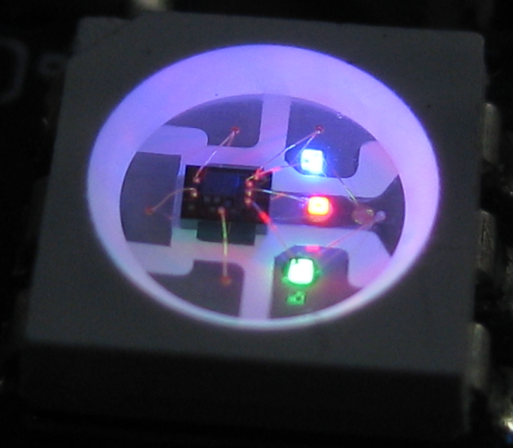
WS2812 (S) светодиод с красным зеленым и синим
Adafruit предлагает множество различных форм и плат со светодиодами NeoPixel, от отдельных светодиодов до полос, колец и матричных плат. Я рекомендую прочитать следующие статьи:
- The Adafruit Überguide : отличная статья, объясняющая все детали WS2812 (под названием «NeoPixel» от Adafruit).
- Блог Тима о WS2812 : мой справочник по всему, что касается светодиодной синхронизации. Он объясняет различия между 6-контактным WS2812 (S) и новым 4-контактным WS2812B.
- Статья о переключателях уровня для WS2812 .
протокол
Каждый пиксель требует 24-битных данных (8-битный красный, 8-битный зеленый и 8-битный синий). Биты смещаются по однопроводному протоколу на вывод DIN (Data In). Немного странно, но биты сдвинуты как зелено-красно-синие (поэтому не RGB). MSB (старший бит) сдвигается первым. Каждый пиксель займет первые 24 бита и сдвинет оставшиеся биты DOUT (Data Out) до следующего светодиода и так далее. Таким образом, светодиоды могут быть легко соединены вместе:
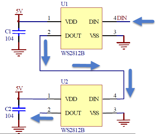
WS2812 Светодиодная цепь
Ниже показан захват потока битов: первая строка — это входной (DIN) вывод первого светодиода, а вторая строка — это выходной вывод (DOUT), всего 4 пикселя. Более широкий импульс отмечает 1 бит, а более короткие импульсы равны нулю. Первый пиксель потребляет первые 24 бита (зелено-красно-синий) и сдвигает остальные 3 × 24 бита. В конце, наличие низкого уровня сигнала в течение 50 мкс зафиксирует биты и покажет их на светодиодах.

WS2812 Bit Stream (нажмите, чтобы увеличить)
Сигнал достаточно быстрый с периодом 1250 нс для одного бита. Нулевой бит кодируется с высотой 350 нс, а один бит кодируется с высоким сигналом в течение 700 нс. Фактическое время зависит от версии пикселей, как описано в этой статье .
Начиная с хлебной доски
As a starter, I ordered 4 bread-board-friendly WS2812(S) NeoPixels to make sure my timing and driver works. Following the Adafruit guidelines, I have put a 400 Ohm resistor between the digital output pin and the first LED. The LEDs need a 5V power supply. While it is possible to get below that, going higher than 5V might destroy the LED. Initially I’m using the 5V from USB, so with a few LEDs no external power supply is needed. Each LED in full brightness needs about 3x20mA, see the Adafruit guide on this topic. For more LEDs, a beefier power supply is needed.
In the picture below I’m not yet using the recommended capacitor of 1000 µF, so make sure you have one added. Because the voltage of the LEDs is 5V, and my microcontroller has 3.3V logic levels, I had to add a level shifter (more about this later). With that setup, my software driver and some wiring, I had the first NeoPixel bright and shiny:
Breadboarding a single NeoPixel
With adding more pixels, I have added the recommended 1000 µF capacitor to avoid an onrush of current which could damage the LEDs. Using a fast logic analyzer is recommended to inspect the signals.

Test Bench Setup with 1000 uF Capacitor added
WS2812 Driver
As the protocol and timing is critical, I used my knowledge with DMA on the FRDM-KL25Z board. The DMA allows me to spit out the bits fast enough, within the timing requirements without loading the CPU too much. I have configured a PWM output pin with a period of 1250 ns, and I’m changing the duty with PWM to encode the zero and one bits.
For the PWM values I use a global buffer in RAM:
#define NEO_NOF_PRE         2 /* somehow need trailing values? */
#define NEO_NOF_BITS_PIXEL  24  /* 24 bits for pixel */
#define NEO_NOF_POST        40 /* latch, low for at least 50 us (40x1.25us) */
#define NEO_DMA_NOF_BYTES   sizeof(transmitBuf)

static uint16_t transmitBuf[NEO_NOF_PRE+(NEO_NOF_PIXEL*NEO_NOF_BITS_PIXEL)+NEO_NOF_POST];
Ideally I would only use 3 bytes of RAM for each Pixel. However, as I need a 16bit value for each PWM duty value, I need 16×3 bytes for each pixel. That’s ok for now, but I already have a different implementation in my mind which will cut down that RAM amount needed.
? There are bit-banging implementations available on the internet which only need 3 byte RAM per pixel. They shift the bits with bit banging with very timing sensitive assembly code. I did not want to implement such a low-level implementation: with sacrificing RAM and using DMA I still have the microcontroller available for doing other things and not keeping the microprocessor busy 100% with the bit shifting.
The PWM is intitialized with period and with DMA enabled:
static void InitTimer(void) {
  TPM_PDD_WriteModuloReg(TPM0_BASE_PTR, TICKS_PERIOD); /* set period */
  TPM_PDD_WriteChannelValueReg(TPM0_DEVICE, 1, 0); /* PWM low, zero duty */
  TPM_PDD_EnableChannelDma(TPM0_DEVICE, 1); /* enable DMA for channel */
}
For the DMA, I configure the source and destination address, along with the DMA transfer size:
static void InitDMA(void) {
  DMA_PDD_SetSourceAddress(DMA_BASE_PTR, DMA_PDD_CHANNEL_0, (uint32_t)&transmitBuf[0]); /* set source address */
  DMA_PDD_SetSourceAddressModulo(DMA_BASE_PTR, DMA_PDD_CHANNEL_0, DMA_PDD_CIRCULAR_BUFFER_DISABLED); /* no circular buffer */
  DMA_PDD_EnableSourceAddressIncrement(DMA_BASE_PTR, DMA_PDD_CHANNEL_0, PDD_ENABLE); /* source address will be incremented by transfer size */
  DMA_PDD_SetSourceDataTransferSize(DMA_BASE_PTR, DMA_PDD_CHANNEL_0, DMA_PDD_16_BIT); /* Transfer size from source is 16bit */

  DMA_PDD_SetDestinationAddress(DMA_BASE_PTR, DMA_PDD_CHANNEL_0, (uint32_t)&TPM0_C1V); /* set destination address */
  DMA_PDD_SetDestinationAddressModulo(DMA_BASE_PTR, DMA_PDD_CHANNEL_0, DMA_PDD_CIRCULAR_BUFFER_DISABLED); /* no circular buffer */
  DMA_PDD_EnableDestinationAddressIncrement(DMA_BASE_PTR, DMA_PDD_CHANNEL_0, PDD_DISABLE); /* no auto-increment for destination address */
  DMA_PDD_SetDestinationDataTransferSize(DMA_BASE_PTR, DMA_PDD_CHANNEL_0, DMA_PDD_16_BIT); /* Transfer to destination size is 16bit */

  DMA_PDD_SetByteCount(DMA_BASE_PTR, DMA_PDD_CHANNEL_0, NEO_DMA_NOF_BYTES); /* set number of bytes to transfer */
  DMA_PDD_EnableTransferCompleteInterrupt(DMA_BASE_PTR, DMA_PDD_CHANNEL_0, PDD_ENABLE); /* request interrupt at the end of the DMA transfer to set new byte count */
  (void)DMA_PDD_GetRequestAutoDisableEnabled(DMA_BASE_PTR, DMA_PDD_CHANNEL_0); /* disable DMA request at the end of the sequence */
  DMA_PDD_EnablePeripheralRequest(DMA_BASE_PTR, DMA_PDD_CHANNEL_0, PDD_ENABLE); /* enable request from peripheral */
}
I have configured it I get a flag set at the end of the DMA cycle. This allows me to check a flag if the DMA transfer is still in progress or not. The flag is reset from the ‘on DMA end interrupt’:
voidMyDMAComplete(void) {
 transferComplete = TRUE;
}
[/sourcecode
Sending the bits over the wire with DMA is then very simple:</pre>
<pre>1
static uint8_t Transfer(uint32_t src) {
  while(!transferComplete) {
    /* wait until previous transfer is complete */
  }
  transferComplete = FALSE;
  DMA_PDD_SetSourceAddress(DMA_BASE_PTR, DMA_PDD_CHANNEL_0, src); /* set source address */
  DMA_PDD_SetByteCount(DMA_BASE_PTR, DMA_PDD_CHANNEL_0, NEO_DMA_NOF_BYTES); /* set number of bytes to transfer */
  DMA_PDD_EnablePeripheralRequest(DMA_BASE_PTR, DMA_PDD_CHANNEL_0, PDD_ENABLE); /* enable request from peripheral */
  return ERR_OK;
}

uint8_t NEO_TransferPixels(void) {
  return Transfer((uint32_t)&transmitBuf[0]);
}
After using the 4 bread board pixels worked fine, I added more pixels with the Adafruit 60 pixel ring, right after the bread board pixels:
Adafruit Neopixel Ring
Video of the pixel ring in action (the bright LEDs created funny pixel artifacts on my camera!):
Level Shifter is Critical!
I was soooooooo happy to see that things are working well. Until I wanted to use the ring without the bread board pixels: the pixels in the ring did not work any more ?
Looking at my bits shifted out of the microprocessor looked fine: the microcontroller was sending 750ns/500ns Bit-1 signal to the first WS2812B pixel. But this 1-Bit signal gets out as 625ns/625ns out of the WS2812B :-(:

Input Ouput Bit 1
Similar picture: I’m sending a 375ns/875 ns 0-bit from the microcontroller, but the first WS2812B makes a 312ns/937ns signal out of it:

Analyzing 2812 ouput
After some heads-scratching and more scoping it was clear: my level shifter was not fast and crisp enough for the WS2812B LEDs :-(. It worked fine for the older WS21812(S) version. And as long as I had a WS2812B as first pixel, that pixel was able to generate the correct signals for the new WS2812B LEDs.
Well, if I only would have found and read http://happyinmotion.com/?p=1247 before…. I had an Adafruit BSS138 available, and while it worked with the WS2812(S), I was wrongly thinking that it would work with the WS2812B too. Well, after the fact it is clear that the pull-ups ruined my signals and my day….
So I have ordered a handful of 74HCT245 to test with and to make it right. Until then, another video with even more pixels in action:
Summary
I think I have been falling in love with these LEDs. They are amazing, and amazing effects can be created with them. It is just that for now my wife does not share that excitment (yet?). Guess I need to work on a more impressive application then… :-). Right now my driver is using to much RAM, so there is for sure room for improvements. While the older WS2812(S) LEDs work with a sluggish level shifter, the new WS2812B need clean signals e.g. from a 74HCT245 (to be verified). Until then a WS2812 as first pixel in the chain helps :-).
The project and sources for Eclipse Kepler are available on GitHub here.